
Measurement Diagrams
The diagrams below are to assist you in determining the correct measurements for identification. These diagrams are intended to be a guideline only. If you are unsure about any measurements please ensure you talk to your parts person for clarification.
End Yokes
Slip Yoke Assemblies
Companion Flanges
Inside Snap Ring U-Joint
Outside Snap Ring U-Joint
Outside Snap Ring/Inside Snap Ring Style
Constant Velocity Head Assembly
End Yokes
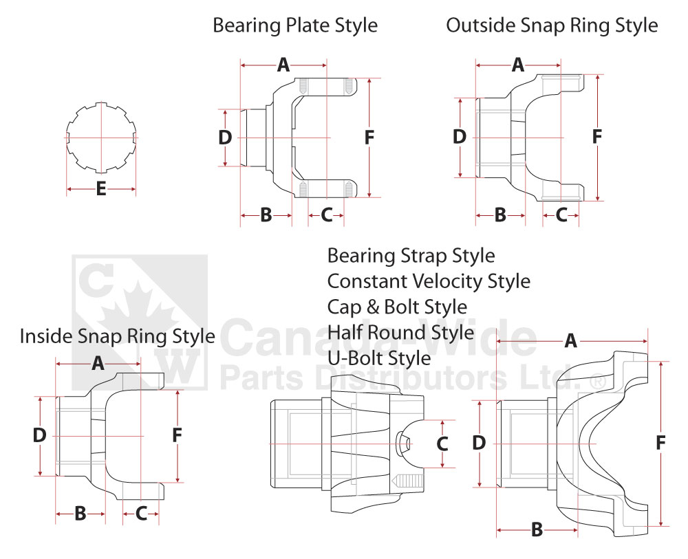
A - Centre to End
B - Thru Hole Length
C - Cap Diameter
D - Ground Hub Diameter
E - Spline Hole Major Diameter
F - Snap Ring to Snap Ring / End Cap to End Cap
Slip Yoke Assemblies
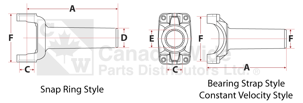
A - Center Line to End of Spline
C - Cap Diameter
E - Spline Hole Major Diameter
F - Snap Ring to Snap Ring / End Cap to End Cap
Companion Flanges
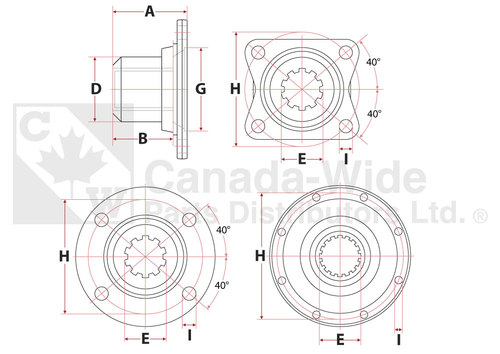
A - Flange Face to End of Hub
B - Length Thru Hole
D - Ground Hub diameter
E - Spline Hole Major Diameter
G - Pilot Diameter - Female/Male
H - Bolt Circle Diameter
I - Diameter - Drilled/Tapped - # of Holes
Inside Snap Ring U-Joint
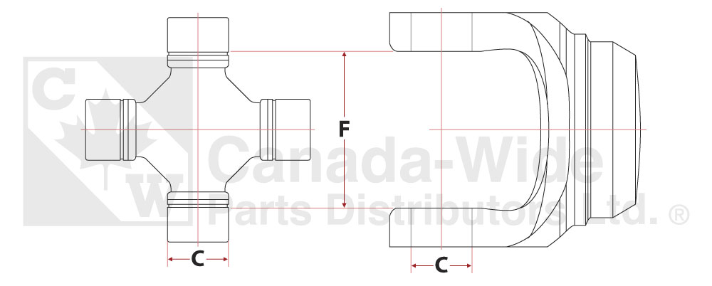
C - Cap Diameter
F - Snap Ring Grove to Snap Ring Grove
Outside Snap Ring U-Joint

C - Cap Diameter
F - End Cap to End Cap
Outside Snap Ring/Inside Snap Ring Style

C1 - Cap Diameter
F1 - Snap Ring Grove to Snap Ring Grove
C2 - Cap Diameter
F2 - End Cap to End Cap
Constant Velocity Head Assembly
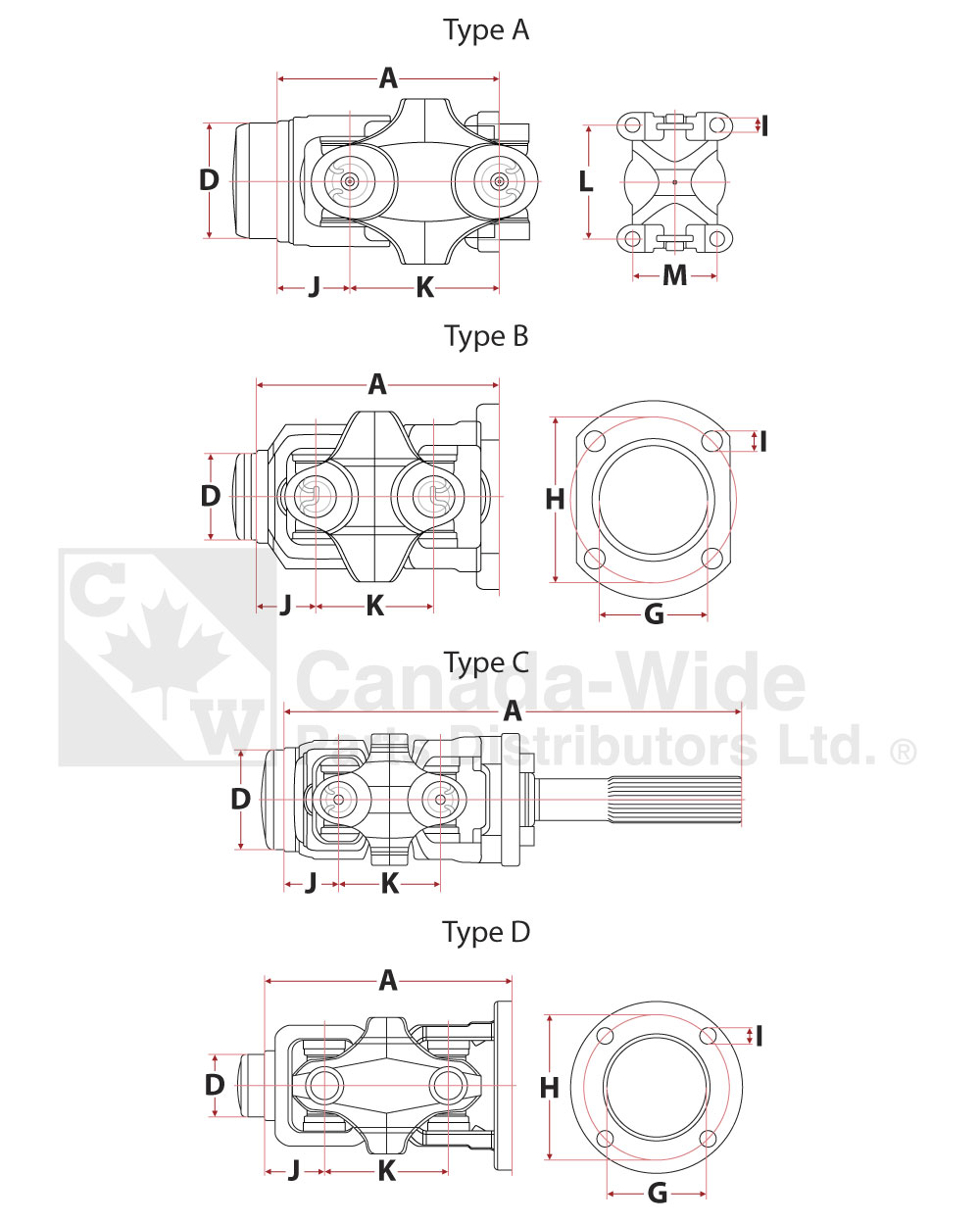
A - Overall Length
D - Butt Diameter
G - Pilot
H - Bolt Circle
I - Bolt Diameter
J - C.L. to Point of Weld
K - C.L. to C.L. of Centre Yoke
L - Hole Spacing Height
M - Hole Spacing Width